
Latest Publication
Carlson, T., Govindjee, S. A fully coupled, electrochemical-magnetic theory with applications to solid-state battery materials. Submitted to JMPS (2025). Link
Most recent note on Mechanics and Mathematics
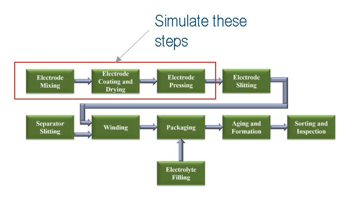
Progress on Manufacturing Simulation and Stress Driven Homogenization of Lithium Ion Battery electrode materials using the Finite Element Method - January 15, 2024
Note: This work will be the subject of an upcoming paper(s?) and is subject to change. Upon completion, this preface will be replaced with a link to the paper(s).
Introduction
Homogenized, finite element, multi-physics simulation of battery performance and aging via the Newman model is an efficient tool that aids in the design of lithium ion batteries at multiple scales. However, the accuracy of these homogenized models depends on the accuracy of the inputs, such as tortuosity and elastic moduli, which can vary drastically between particular battery microstructures. As such, it is vital that homogenized properties corresponding to the real microstructure are used in simulation. However, the derivation of these properties often requires experimental results or 3d images of electrode microstructures, both of which can be difficult, expensive, and time consuming to obtain. Therefore, it is desirable not only to derive effective microstructural properties of electrode materials through simulation, but also the electrode materials themselves.
Existing first principles and DEM simulation methodologies for microstructure generation [3] allow for explicit consideration of the CBD phase and the effects of calendaring, but do not allow for generation of microstructures with complicated particle geometries and do not allow for simulation of particle fracture or plastic deformation at the RVE scale. Algorithmic generation (e.g. MATBOX [8]) of electrode materials allows for the consideration of more complicated geometries, but does not allow for consideration of calendaring pressure as an input parameter and does not allow for efficient homogenization of elastic properties at the RVE scale due to the nontrivial task of meshing these geometries. Further, the inputs of these algorithms tend to be quantities that would generally not be known prior to manufacturing (final porosity after calendaring, for example). In the present work, a method of simulating the manufacturing process of electrode materials using the finite element method with an implicitly considered CBD phase is proposed, wherin CBD is added to a resultant RAW image file in post processing. Further, the effective elastic tensor is derived and calculated for a microstructure with an implicitly considered second phase. This work, when coupled with other recent work on battery microstructure homogenization and simulation [6], allows for a complete "digital twin" for electrode materials, enabling simulation and optimization of battery materials at multiple scales.
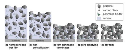
Manufacturing of electrode materials is a complex, multi-step process wherein active materials are mixed and homogenized in a slurry, applied to a current collector, dried, and pressed to achieve an energy dense electrode material that can be further processed to create a battery. During the mixing process, electrode particles, polymeric binder, and carbon black are mixed and homogenized in a slurry. After this step, the slurry is applied via spraying, for example, to a current collector where it drys. During this step, the film shrinks, the solvent is removed, and the polymer and carbon black bind together to form the nanoporous CBD phase which acts as a mechanical and electrical connection between active material particles. Finally, the dried electrode microstructure is compressed in the calendaring step, where porisity is decreased to increase the energy density of the material [2]. A major objective of this work is to effectively simulate these steps, which constitute the first major parts of the electrode manufacturing process. While the later steps, such as electrolyte filling, are important to the function of the battery, they generally do not impact the characteristics of the microstructure that this work seeks to computationally capture.
This work utilizes the finite element method to simulate each of the steps of this process which, in principal, allows for the consideration of arbitrary active material geometry and for a more robust consideration of material properties at the millimeter scale, such as plasticity. However, in the present work, only linear elastic properties and ellipsoidal geometries are considered.
Manufacturing Simulation
Slurry Homogenization and Consolidation Simulation
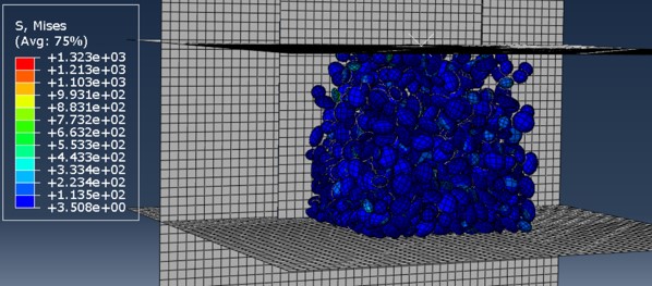
The active material particles in slurry are simulated as a collection of geometric shapes of varying sizes distributed randomly via a given particle size distribution (psd). In the present work, the geometries considered are limited to ellipsoids with a uniform major to minor axis ratio, and the psd is given as a discrete collection of major axis lengths and their probability of occurrence. A python script was created that generates a bounding box made of rigid (R3D4) plates, all of the particles at a given mesh (C3D8R) resolution, and places all of the particles within the box. The script was formulated so that, if desired, arbitrary geometries could be generated and placed within a box with sizes depending on a given (continuous or not) particle size distribution, but these features are not utilized in the present work, as finite element simulation of ellipsoidal particles already achieves a greater correspondence to real electrode microstructures than most state-of-the-art modelling methods.
During the homogenization and consolidation steps, the particles in their initial positions are allowed to move freely with gravity in an an explicit, dynamic Abaqus simulation. In order to facilitate mixing and achieve a given initial porosity, the outer boundaries of the bounding box are moved inwards, which causes the initially uniformly placed particles to collide and homogenize. After the walls are moved to their designated position based on a given target porosity, the particles are allowed to settle during a long relaxation step. During this process, the particle to particle contact conditions and the particle to boundary contact conditions are hard and frictionless, as there should not be any cohesive force or friction between the particles in slurry. However, the script used to generate the Abaqus input file allows for alternative contact models during mixing, if desired. Additionally, because the effects of self weight of the particles on the final material microstructure are assumed to be negligible, particle mass was optimized to minimize both simulation time and particle weight, but also kept low enough to ensure p-wave speeds remain small.
Note that since the slurry is only considered implicitly, (i.e. only the active material is modelled explicitly), it is assumed that the geometry resulting from the consolidation/homogenization process is independent of the physical properties of the slurry.
Drying Simulation
Given that the electrode drying process is not simulated explicitly and that modelling the CBD particles would necessitate consideration of a much smaller scale, the drying of the electrode and, by extension, the mechanical properties of the CBD are modelled through a change in the contact conditions between particles after settling. The drying is simulated implicitly through the settling of particles due to gravity and the change in the contact conditions, where the frictionless, hard contact changes to a cohesive contact model. In this model[9], separation between two surfaces is modeled through the following equation:
Where \(\boldsymbol{t}\) denotes the traction at the surface interface, \(\boldsymbol{\delta}\) is the separation between the two surfaces, \(K_{nn}\) denotes the constant in the linear relationship between traction and separation in the normal direction, and \(K_{tt}\) and \(K_{ss}\) are the constants in the linear relationship between traction and separation in the two shear directions. Since the CBD is assumed to be isotropic, \(K_{tt}=K_{ss}\). Further, it is assumed that \(K_{tt}\) and \(K_{nn}\) are approximately the homogenized Young and shear modulus of the CBD, as the separation corresponds to the normal and shear components of the displacement. Note that although Abaqus allows for damage to occur between cohesive contacts, this is not considered in the present work. Further note that during the drying and subsequent steps, contacts made between active material particles not initially in contact at the beginning of the drying step are not assumed to also form CBD contacts, and instead have an assumed friction. However, if it is assumed that the CBD particles tend to stick together when they come into contact with one another even after drying, then this contact condition could be adjusted accordingly.
Electrode Calendaring
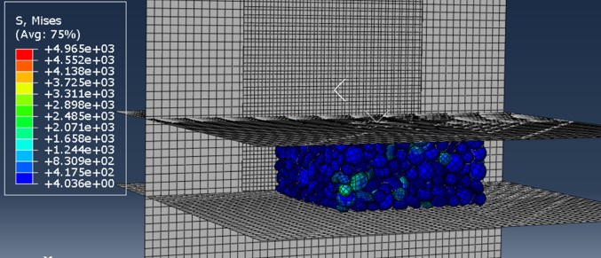
In this step, the top of the bounding box is brought in contact with the electrode surface, and the outer boundaries of the bounding box are adjusted outwards to allow for uniaxial compression of the electrode material. Then, uniaxial compression is applied to the microstructure via a specified pressure on the upper surface of the bounding box which corresponds to the area of the dried electrode material. After calendaring, pressure (aside from atmospheric pressure to prevent the upper plate from escaping) is removed to allow the electrode to equalibriate. During this step (and all others, for that matter), deformation of the particles is linear elastic, meaning that the (Cauchy) stress in each particle is of the form
\[ \mathbf{\sigma}=\mathbf{C}:\mathbf{\epsilon} \]where : denotes double contraction of tensors, and where \(\mathbf{C}\) is the elastic tensor for the active material defined through Young's modulus and the Poisson ratio, as these materials can be assumed isotropic, and \(\mathbf{\epsilon}\) is the strain.
Post Processing: Geometric CBD addition
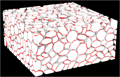
Given that the CBD was only implictly considered in the Abaqus simulation, a CBD phase must be added to the 3D microstructure. This is accomplished by first converting the final microstructure to a RAW file by utilizing an existing Abaqus plugin that converts ODB output to STL files, and then by using a C++ code to convert the STL to a 3D RAW image. Then, a C++ code adds a third CBD phase to the raw file via a maximal inscribed sphere calculation which associates spheres in a certain radius threshold to electrolyte (pore) and active particles depending on a input value for final CBD volume fraction [10]. The volume not associated with these spheres is then assigned as the CBD phase. This step is not necessary for the homogenization of elastic properties, but it is necessary for further study and homogenization of electrochemical and thermal properties of the resulting microstructure for use in a homogenized multi-physics battery simulation, or for a fully resolved electrochemical simulation of the anode. These subsequent simulations are to be objectives of future work not studied herein.
Stress Driven Homogenization
Preliminaries
Abaqus allows for fully coupled electrochemical-thermal-mechanical-pore pressure simulation of battery multiphysics. If the generated microstructures are to be useful in these simulations, representative elastic moduli must be derived. Given that the strain in the CBD phase is only known via the stress on the particle boundaries, a stress driven approach is used to derive the effective elastic compliance tensor, \(\overline{\mathbf{D}}\).
We begin by noting the assumptions made regarding the CBD:
- CBD is only present at points with nonzero contact stress
- The stress in the CBD is uniform and equal to the stress at the point(s) of contact
- The deformation of the CBD is homogeneous at each point where it is assumed to exist
- The initial thickness of the CBD is equal to \(l_0\)
- The same volume of CBD, \(V_{c}\), is present at all points where CBD is assumed to exist
Derivation
Let particles \(i\) and \(j\) have surfaces \(S_i\) and \(S_j\) that have some contact area \(A_{ij}\). If two points in \(A_{ij}\) are deformed from their initial contact position, the vector from one point to the other will be \(\mathbf{\delta}\) in the deformed configuration. However, given that the initial separation of the points \(l_0\mathbf{n}\) isn't explicitly considered, where \(\mathbf{n}\) is the normal vector at one of the points, it must be the case that
Where \(\mathbf{F}=\mathbf{1}+\nabla \mathbf{u}\) is the deformation gradient and \(\mathbf{u}\) is the displacement vector. Therefore,
Given that it is assumed stress and strain are assumed homogeneous in each CBD region, \(\mathbf{\sigma}\) and \(\nabla \mathbf{u}\) are constant over each region \(A_{ij}\). However, it need not be the case that \(\mathbf{n}\) is constant; in fact, \(A_{ij}\) is essentially arbitrary. Therefore, it must be the case that
Then, it must be the case that the strain energy \(W_{CBD}\) in the CBD phase is
where \(\mathbf{\sigma}\) denotes the stress in the CBD, determined by the stress in the particle, and \(\mathbf{\epsilon}\) is the symmetric part of the displacement gradient.
It will be assumed that the full, three-phase (air, CBD, active material) microstructure generated will have a boundary condition of the form \(\mathbf{\Sigma}\mathbf{n}=\mathbf{\overline{t}}\). By the Hill-Mandel Complementary Theorem, The macroscale complementary virtual work is equal to the average complementary virtual work inside the RVE. Furthermore, it is known that, in this case, the average microscale stress and strain are equal to the macroscale stress and strain, respectively [1]. Then, if \(\mathbf{\Sigma}\) is the macroscale stress, then the following functional
is maximized when the volume average of \(\mathbf{\sigma}\) corresponds to the macroscale stress field \(\mathbf{\Sigma}\)[4], where \(\mathbf{E}=\frac{1}{V}\int \mathbf{\epsilon}(\mathbf{\sigma})dv\) is the macroscale strain and \(\mathbf{d}\) is the displacement.
Taking the first variation with respect to \(\mathbf{d}\) and noting the maximization principle,
Which implies that \([\overline{W^c}_{,\mathbf{d}}]=0\) since \(\delta\mathbf{d}\) is arbitrary. Thus,
At this point, FEA concepts must be introduced. In the CBD, \(\mathbf{\epsilon}=\mathbf{R}\text{sym}(l_0^{-1}(\mathbf{K}^{-1}\mathbf{\sigma_i}))\mathbf{R}^T\), and so \(\mathbf{\epsilon}=\text{sym}(l_0^{-1}(\mathbf{R}\mathbf{K}^{-1}\mathbf{\sigma_i})\mathbf{R}^T)\), and \(\mathbf{\sigma}=\mathbf{C}\mathbf{B}^e_i\mathbf{d}^e\) where \(\mathbf{\sigma_i}\) denotes the stress in the CBD in the local directions relative to the surface normal determined by the stress at a contact point, \(\mathbf{B}^e_i\) is the evaluation of the element \(\mathbf{B}\) matrix at the contact point, \(\mathbf{d}^e\) is the element displacement vector, and \(\mathbf{R}\) is the rotation matrix translating the local stress to the (XYZ) coordinate system (i.e. \(\mathbf{\sigma}_i=\mathbf{R}\mathbf{\sigma}\mathbf{R}^T\)). Therefore, the relation for \(\mathbf{\epsilon}\) can be written \(\mathbf{\epsilon}= \text{sym}(l_0^{-1}(\mathbf{R}\mathbf{K}^{-1}\mathbf{R}^T\mathbf{\sigma}))\).
In the active material
In the CBD, these relationships are
by the symmetries of \(\mathbf{C}\), where (10) comes from differentiation of (5), and \(\mathbf{D}_c\) is defined by
where \(\mathbf{K}_*=\mathbf{R}\mathbf{K}^{-1}\mathbf{R}^T\).
Given that the points of contact are taken to be nodes, the normal at a node is taken to be the average of the normal vectors of the adjacent elements. Then, if \(\mathbf{u_1}\) and \(\mathbf{u_2}\) are two vectors that form an orthonormal basis with the normal \(\mathbf{n}\), then it must be the case that
Where each of the vectors are columns in the rotation matrix. For the actual computer implementation, the equations in (10) should be multiplied by \(\delta(P)V_c/2\) since the stress and strain are constant over the volume of the CBD located at that point, where \(P\) denotes the coordinates of any point where elements are in contact and \(\delta\) is a multi-point delta function. A factor of 2 is introduced to account for the fact that CBD is double counted by reaction forces.
Letting \(\mathscr{A}\) denote the assembly operation, then plugging the previous equations into (8) and solving for \(\mathbf{d}\) yields
Then, since \(\mathbf{\overline{D}}=\mathbf{E}(\sigma(\mathbf{d}))_{,\mathbf{\Sigma}}\)
Where \(\mathbf{M}\) is the term preceding \(\mathbf{\Sigma}\) in (13) Noting the relationships defined above, with the CBD taken into account (14) becomes
Note that \(\mathbf{C}\mathbf{R}\mathbf{K}^{-1}\mathbf{R}^T\mathbf{C}\), \(\mathbf{D_c}\mathbf{C}\), and \(\mathbf{C}\mathbf{D_c}\) are handled as fourth order tensors in voight notation before multiplication with the \(\mathbf{B}\) matrix.
In the final computer implementation, reduced integration elements are used. Therefore, the integrals in (14) and (15) reduce to
where \(\sum_{i=1}^{N^s_e}\) denotes the number of points in contact, \(V_e\) denotes the integration point volume, and \([\mathbf{B}^e]_0\) is the value of the element \(\mathbf{B}\) matrix computed at the integration point (i.e. the element centroid).
Example Simulations
For the microstructure example microstructure given, the following inputs were provided
- 10 particles generated in each direction with major axis lengths of 15\(\mu\)m (50%) and 10\(\mu\)m (50%) and a major to minor axis ratio of 2.
- The particles were assumed to be made of isotropic graphite, (\(E\)=32470 MPa, \(\nu\)=0.32) [7]
- The calendering pressure applied in the manufacturing simulation was 10 MPa
- The homogenized CBD properties were assumed to be \(E\)=63.8 MPa and \(G\)= 24.5 MPa per [5]
- The friction coefficient between particles not initially in contact was assumed to be 0.2
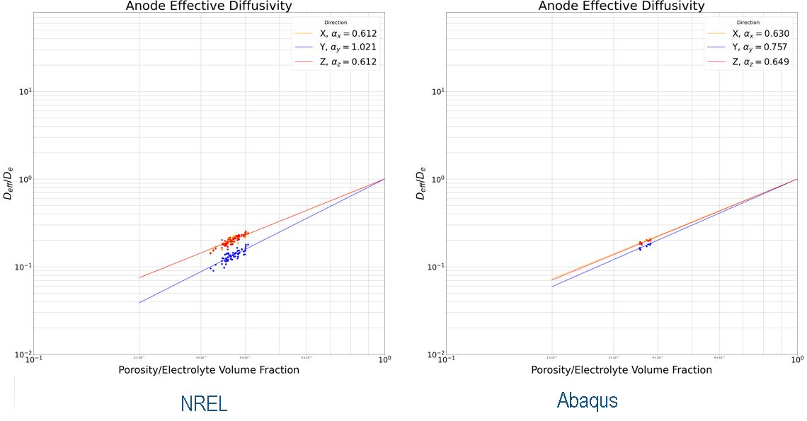
Diffusivity in the electrolyte phase prior to calendaring was compared against microstructures generated by NREL [8] via a random walk diffusion methodology. Given that these microstructures were generated to match calendared electrodes and verified accordingly, the results are reasonable given that calendaring is expected to increase tortuosity in the thickness direction. The calendaring pressure applied in the Abaqus simulation is low in comparison to typical electrodes.
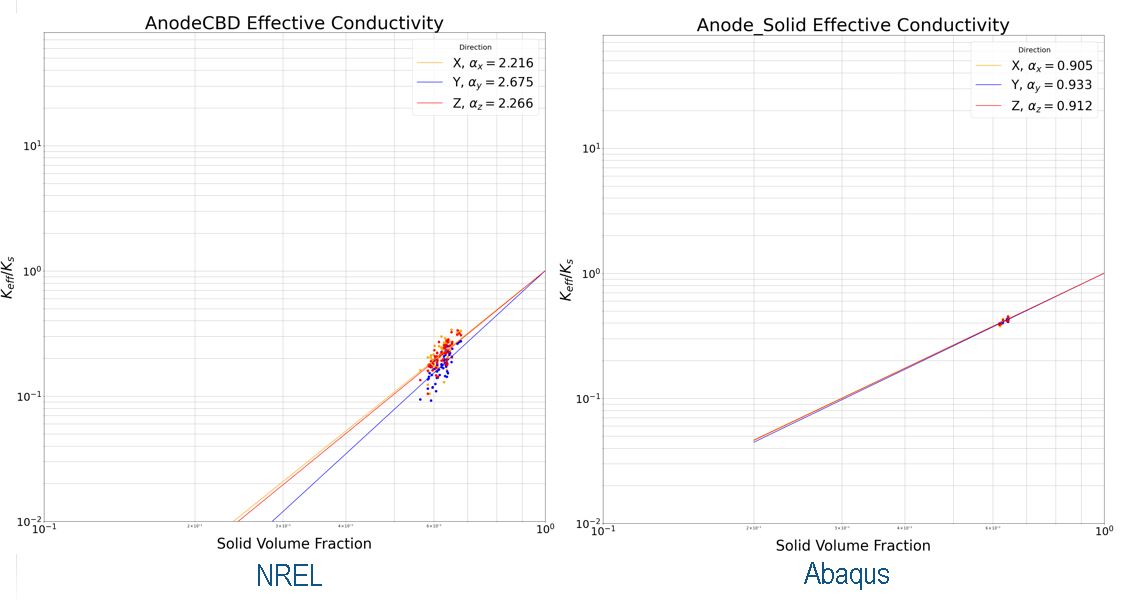
Conductivity in the solid phase prior to calendaring was compared against microstructures generated by NREL via a similar random walk methodology. Apart from similar differences in anisotropy due to calendaring, there is much more intimate particle to particle contact in the microstructure generated in Abaqus, which likely leads to a greater conductivity. Future work should implement contact erosion in post processing in order to replace unrealistically intimate contact with CBD.
The homogenization procedure was implemented in the abaqus scripting interface to allow for efficient utilization of the microstructure output from the manufacturing step. (E\_hom.py - github link TBD)
Concluding Remarks
In the future, a homogenization process for the CBD phase given a certain weight percentage and parameters relating to the drying process would allow for a more complete digital twin of the simulation process. Obviously, further validation and calibration of the contact model with data from real electrodes with known CBD properties, calendaring pressure, and active material particle size distribution would aid in the practical utility of the method.
In the future, computation of homogenzied elastic properties of subvolumes of the RVE to generate relationships between porosity and elastic properties could be used for further resolution of continuum multiphysics battery models at higher scales [6].
Acknowledgements
Special thanks to Dr. Rafael Salazar-Tio for his guidance relating to the CBD addition in post processing and the random walk diffusion/conductivity calculations. This work would also not have been possible without software and computers provided by Dassault Systemes.
References:
- Shaofan Li, Gang Wang, Introduction to Micromechanics and Nanomechanics, 2017
- Blake Hawley, Jianlin Li, Electrode manufacturing for lithium-ion batteries—Analysis of current and next generation processing, 2019
- Ngandjong et. al., Investigating electrode calendering and its impact on electrochemical performance by means of a new discrete element method model: Towards a digital twin of Li-Ion battery manufacturing, 2020
- Shaofan Li, Yuxi Xie, A stress-driven computational homogenization method based on complementary potential energy variational principle for elastic composites, 2020
- Grillet et. al., Conductivity degradation of polyvinylidene fluoride composite binder during cycling: Measurements and simulations for lithium-ion batteries, 2016
- Carlson et. al., Method for electrochemistry modeling of Li-ion Battery by upscaling from microstructure to continuum using a mesoscale, heterogeneous homogenization, 2023
- Qi et. al., Threefold Increase in the Young’s Modulus of Graphite Negative Electrode during Lithium Intercalation, 2010
- Usseglio-Viretta et. al., MATBOX: An Open-source Microstructure Analysis Toolbox for microstructure generation, segmentation, characterization, visualization, correlation, and meshing, 2021
- Abaqus Theory Manual, Dassault Systemes.
- Ganapathi RAMAN Balasubramanian et. al., Numerical Characterization of Physical Properties of Microstructures in Lithium-Ion Batteries, 2022
-TJC